Capping Machines
Used Capping Equipment
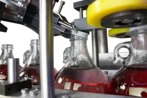 Frain Industries is the world leader in providing used capping machine and equipment solutions. Frain carries several types of cappers covering a wide range of caps including metal, plastic, screw, lug, roll-on, crimp-on, press-on, plastic shrink, plugs, fitments, inner seals. Additionally there are many types of capping systems depending on the container and cap type.
Frain Industries offers capping equipment and machines in semi-automatic and automatic capper configuration, intermittent or continuous motion, as well as inline and rotary. The Frain engineering team can design a capping solution based on your product, application, line speed, and line integration requirements.
- Chuck Capping Machines
- Spindle / Screw Capping Machines
- Cap Tighteners / Retorquers
- Snap Capping Machines
- Roll Over Pilfer Proof Capping Machines
- Press / Push-On Capping Machines
- Pump (Trigger Pumps, Dosing Pumps) Capping Machines
- Crimp Capping Machines
- Crowner Capping Machines
- Lidding Machines
- Steam Vacuum Capping Machines
Frain Industries carries used capping machines from many OEM’s including Accutek, Aidlin, Akra Pak, Alcoa, Anderson, Autoprod, Axon, Bausch & Strobel, Consolidated, Cozzoli, Culbro, Del Packaging, Donahower, E Pak, Elf, Enercon, Filamatic, Filma-Seal, Fuju, Groninger, Holmatic, Hoppmann, Hypak, Kalish, Kaps All, King, Kinsley, Kiss Packaging, Krones, Lepel, Marburg, McKenna, Mengibar, Meyer, MRM Elgin, New England, New Jersey, Newman, Owens, Pack West, PDC International, Perry, Pillar, PMC, Pneumatic Scale, PPS, Reed, Resina, SureKap, Swan-Matic, Thiele, US Bottlers, Universal Machine, Weco, West, White Cap, Zalkin , and many others.
Related Categories
Capping Equipment In Stock
Fowler Capper Chuck CAS-3/360
- Manufacturer: Fowler
- Model Number: CAS-3/360
- Frain Number: 5J4560
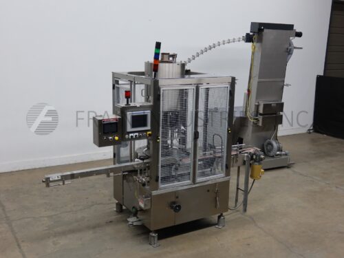
Fowler, Model CAPD-3/360, (3) head rotary chuck capper. Rated from 15 to 75 containers per minute – depending on materials, application and machine configuration. Incline cleated cap feeder equipped with a 36" long x 36" wide x 26" deep hopper, 8½" wide belt with 2" high cleats on 8¾" centers and a 125" discharge. Capper equipped with a 40" diameter bowl sorter, 7½" wide belt conveyor with single worm screw to star wheel indexing and (3) head chuck cappers set on 12" centers. Control panel has AB controller and touch screen HMI. Mounted on heavy duty frame with safety guarding.
OAD: 108"L x 58"W x 120"H – Capper
118"L x 45"W x 148"H – Incline Feeder
SureKap Capper Quill SK6000-BF6
- Manufacturer: SureKap
- Model Number: SK6000-BF6
- Frain Number: 5J4441
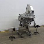
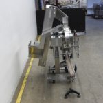
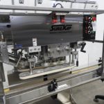
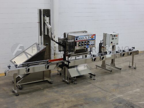
SureKap, model SK6000 BF6, automatic, inline, stainless steel, 3 station, 6 spindle roll over conveyor capper and cap feeder with number of containers per minute – depending on materials and application Cap size range: 22mm to 70mm. Equipped with 144" long x 4½" wide stainless steel container conveyor, 24" long x 18" wide x 24" deep cap hopper, 77" long x 6" wide elevator with 2½" high cleats on 6" centers, 46" long x 6" wide cap feeding / sorting belt, adjustable cap chute, with 24" long x 2" wide single container gripper belts, (3) hand crank adjustable (6) spindle stations (2) sets of mechanical clutches for increased torque control. Control panel with spindle and gripper control dials, start and e-stop buttons. Mounted on heavy duty stainless steel frame with casters.
OAD: 144"L x 72"W x 99"H
Get a Free Quote Call: 630-629-9900Resina Capper 1 Head (Capper) S30
- Manufacturer: Resina
- Model Number: S30
- Frain Number: 5J4800
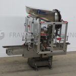
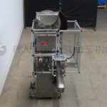
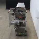
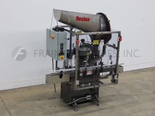
Resina, Model S30, Automatic single head chuck capper with number on containers per minute – depending on materials, application and machine configuration. Cap size range: 13mm to 120mm. Containers size range: to 6" in Diameter and 6" to 15" in Height. Equipped with 84" long x 4½" wide stainless steel container conveyor, cap hopper with disc pin sorter, cap chute, transfer shoe with cap button, dual container grippers and single head chuck style cap tightner, has start, stop push buttons. Mounted on base frame with safety door guarding. Change parts required to accommodate different size ranges.
OAD: 101"L x 48"W x 86"H
Get a Free Quote Call: 630-629-9900Resina Capper 1 Head (Capper) S30
- Manufacturer: Resina
- Model Number: S30
- Frain Number: 5J5070
Resina, Model S30, automatic single head chuck capper with number on containers per minute – depending on materials, application and machine configuration. Cap size range: 13mm to 120mm. Containers size range: to 6" in Diameter and 6" to 15" in Height. Equipped with 70" long x 4½" wide container conveyor, cap hopper with disc pin sorter, cap chute, transfer shoe with cap button, single container grippers and single head chuck style cap tightner, has start, stop push buttons. Mounted on base frame with safety door guarding. Change parts required to accommodate different size ranges.
OAD: 76"L x 47"W x 89"H
Get a Free Quote Call: 630-629-9900Pneumatic Scale Capper 8 Head of More 3360
- Manufacturer: Pneumatic Scale
- Model Number: 3360
- Frain Number: 5J4111
Pneumatic Scale, Model 3360, 8 head chuck capper and cap feeder rated from 40 to 120 containers per minute – depending on materials, application and machine configuration. Maximum Cap size: 110mm. Maximum container size: 8" diameter. Equipped with 4½" wide container conveyor, 51" wide x 48" long x 32" deep bulk cap hopper, 29½" wide waterfall sorting belt conveyor with (5/8)" cleats set on 5¼" centers. Control panel has touch screen HMI. Mounted on heavy duty frame with safety guarding and adjustable leveling legs.
OAD: 77"L x 58"W x 133"H Cap Sorter
157"L x 90"W x 120"H Capper
Pneumatic Scale Capper 8 Head of More TC-450-8
- Manufacturer: Pneumatic Scale
- Model Number: TC-450-8
- Frain Number: 5J4110
Pneumatic Scale, Model TC-450-8, 8 head chuck capper and cap feeder rated up to 200 containers per minute – depending on materials, application and machine configuration. Maximum Cap size: 100mm. Maximum container size: 6¼" diameter. Equipped with 4½" wide container conveyor, 41" wide x 48" long x 32" deep bulk cap hopper, 29½" wide waterfall sorting belt conveyor with (5/8)" cleats set on 4¼" centers. Control panel has touch screen HMI. Mounted on heavy duty frame with safety guarding and adjustable leveling legs.
OAD: 80"L x 53"W x 153"H Cap Sorter
144"L x 55"W x 105"H Capper
Consolidated / Pneumatic Scale Capper Fitment Applicator HOF
- Manufacturer: Consolidated / Pneumatic Scale
- Model Number: HOF
- Frain Number: 5C6684
Automatic snap capper capable of 20 to 200 containers per minute. Equipped with 3-1/4" conveyor, cap hopper, pin wheel sorter, air assist cap chute and star wheel container handling components.
OAD = 108" L x 40" W x 96" H
Get a Free Quote Call: 630-629-9900Zalkin Capper 4 Head (Capper) CA3PM
- Manufacturer: Zalkin
- Model Number: CA3PM
- Frain Number: 5C4772
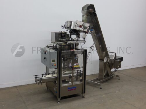
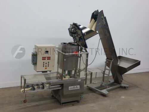
Stainless steel, 3 head rotary capper capable of speeds from 40 up to 105 cpm. Cap range from 15-63mm. Container size range: dia of 85mm (3-3/8) & max ht of 250 (10"). Equipped with screw in feed to star wheel, 3-1/2” wide conveyor with variable speed controls. Screw feed left to right product flow. Available at an additional cost model ECT cap feeder /hopper, 8” (W) x 2 1/2” (H) cleated cap elevator set on 5” centers.
Get a Free Quote Call: 630-629-9900SureKap Capper Quill SK6000-BF6
- Manufacturer: SureKap
- Model Number: SK6000-BF6
- Frain Number: R34825
SureKap Model SK6000 BF6-70, automatic, inline, stainless steel, 3 station, 6 spindle roll over conveyor capper and cap feeder with number of containers per minute – depending on materials and application Cap size range: 22mm to 70mm. Equipped with 120" long x 4-1/2" wide stainless steel container conveyor, 21" long x 25" wide x 18" deep (4 ft³) cap hopper, 77" long x 6" wide elevator with 2½" high cleats on 6" centers, 46" long x 5½" wide cap feeding / sorting belt, adjustable cap chute, with 24" long x 1" wide single container gripper belts, (3) hand crank adjustable (6) spindle stations (2) sets of mechanical clutches for increased torque control. Control panel with spindle and gripper control dials, start and e-stop buttons. Mounted on heavy duty stainless steel frame with casters.
OAD: 120" L x 40" W x 63" H
Get a Free Quote Call: 630-629-9900E Pak Capper Quill 8 SPINDLE
- Manufacturer: E Pak
- Model Number: 8 SPINDLE
- Frain Number: R35303
E Pak, Automatic, inline, stainless steel, feeder, spindle capper, conveyor and cap inspection. Rated from 10 to 90 containers per minute – depending on materials, application and machine configuration. Cap size range: 32mm to 130mm in Diameter. Equipped with a waterfall style cap sorter with a 47" long x 37" wide x 22" deep hopper and 9" wide belt with 3/8" high cleats set on 2" centers, adjustable cap chute, 4½" wide x 240" long Delrin belt, 32" long double container gripper belts, 4 station / 8 spindle capper and cap inspection with reject to identify missing, crooked or high caps. Control panel has push button start / stop controls and variable speed controls. Mounted on heavy duty base frame.
OAD: 240"L x 57"W x 71"H (Capper)
50"L x 46"W x 105"H (Feeder)
E Pak Capper Over Lidder SNAP CAPPER
- Manufacturer: E Pak
- Model Number: SNAP CAPPER
- Frain Number: R35112
E Pak, automatic, inline, stainless steel, snap cap feeder, capper and conveyor. Rated from 10 to 90 containers per minute – depending on materials, application and machine configuration. Cap size range: 32mm to 130mm in Diameter. Equipped with a waterfall style cap sorter with a 47" long x 50" wide x 20" deep hopper and 23½" wide belt with ½" high cleats set on 5½" centers, adjustable cap chute, 4½" wide x 144" long Delrin belt, 24" long double container gripper belts and 3" wide x 10" long top compression belt. Control panel has push button start / stop controls and variable speed controls.
Mounted on heavy duty base frame.
OAD: 150"L x 51"W x 66"H (Capper)
58"L x 50"W x 125"H (Feeder)
Resina Capper 1 Head (Capper) S30
- Manufacturer: Resina
- Model Number: S30
- Frain Number: 5J4410
Resina, Model S30, Automatic single head chuck capper. Cap size range: 13mm to 70mm. Containers size range: up to 6" in Diameter and 6" to 15" in Height. Equipped with 96" long x 4½" wide stainless steel container conveyor, cap elevator, cap hopper with disc pin sorter, cap chute, transfer shoe with cap button, dual container grippers and single head chuck style cap tightner. Touch screen HMI. Speed dependent on materials, application and machine configuration. Change parts required to accommodate size range.
OAD: 100"L x 52"W x 102"H
Get a Free Quote Call: 630-629-9900